
NETGEAR M4500
ProSAFE Intelligent Edge Managed Switch
Our Price: Request a Quote
More pricing below, click here!
Please Note: All Prices are Inclusive of GST
Overview:
Introducing two new, preconfigured M4500 100GE switches: M4500-32C and M4500-48XF8C. The trend of moving matrix switching into the Ethernet network is accelerating and a new class of switches has come to market. Combining the configurability of a matrix switch with the power and scalability of Ethernet, they support hundreds of AV over IP endpoints, at a price point dramatically lower than comparable matrix switches. The Layer 3 feature set includes static and dynamic routing with VRRP, OSPF, BGP, VRF-Lite and PIM. Removing the need for PIM routing, these new switches offer IGMP Plus and greatly simplify system architectures with the same well-known IGMP techniques across the entire AV over IP network while still operating at Layer 2. Installers opting to use M4500-48XF8C switch in their installation will find that it is already preconfigured out of the box. It comes with 48 10G Fiber ports with 8 100G uplink ports with true AV and multicast Zero Touch network configuration. Connect AV over IP encoders and decoders, and power on the switch. It just works! Then use the M4500-32C switch to aggregate the edge switches for a complete set up in large projects up to 320x320 SDVoE (10Gb) devices in a single architecture.
A 10G to 100G solution
- The M4500-32C offers 32-port QSFP28 preconfigured for 100G and can support 40G QSFP+ and 50G QSFP28 optics or DAC cables
- The M4500-48XF8C offers 48-port SFP28 preconfigured for 10G with 8-port 100G QSFP28 uplinks, and the SFP28 ports can support 10G and 25G
For Pro AV Installations
- Installers opting to use M4500 switches in their installation will find that it is already preconfigured out of the box
- True AV and multicast Zero Touch network configuration: Connect AV-over-IP encoders and decoders, and power on the switch. It just works! Intelligent IGMP Plus
Intelligent IGMP Plus
- IGMP Plus multicast allows for scalable Pro AV installations at Layer 2 without the PIM (Protocol Independent Multicast) complexity
- IGMP Plus is default on VLAN 1 out of the box and can be configured on another VLAN for automatic IGMP across M4500 and M4300 switches on that VLAN
Higher availability
- Meet the requirements of high performance, high availability, fast scale out, low latency performance, and continuous serviceability in sensible applications
- The M4500 switches offer 1+1 power and 4+2 fan redundancy, an x86 Intel Atom® Processor C3558 with 8GB DDR3/ECC RAM and 128GB SSD storage
Industry standard management
- The M4500 switches come with an industry standard command line interface (CLI), SSH, SNMP, sFlow, and MLAG
- An out of band 1 Gigabit Ethernet port facilitates management, with simplified macro-commands for AV-over-IP configuration
Industry leading warranty
- NETGEAR M4500 series is covered under NETGEAR ProSAFE Limited Lifetime Hardware Warranty*
- 90 days of Technical Support via phone and email, Lifetime Technical Support through online chat and Lifetime Next Business Day hardware replacement
Features:
Built for AV over IP
NETGEAR IGMP Plus™ enables instant multicast functionality for most AV over IP installations
Cost effective 100G aggregation and 10G access layer for AV deployments and redundant spine & leaf topologies
ptimized for "Spine and Leaf" redundant AV installations, with or without MLAG between spine switches
Up to 320 TX / 320 RX (10 Gigabit) nodes all line rate with each other in a redundant spine and leaf architecture
IGMP Plus is default on VLAN 1 out of the box and can be configured on another VLAN for automatic IGMP across switches on that VLAN
2 power supply units (APS750W) and 6 redundant fan trays (AFT402) pre-installed for 1+1 power and 4+2 fan redundancy
Software Features
Advanced IPv4/IPv6 security including malicious code detection, DHCP Snooping, IP Source Guard, and Control Plane Policing (CoPP)
Selectable Port-Channel / LAG (802.3ad - 802.1AX) L2/L3/L4 hashing for fault tolerance and load sharing with any Ethernet channeling
Up to 64 Link Aggregation Groups (LAG, Port-Channel, LACP) with 32 ports per LAG and Multi-chassis Link Aggregation (MLAG)
IPv4/IPv6 static and dynamic routing including IP Multinetting/CIDR, PBR, VRRPv2, OSPFv3, PIM-SM6, BGP4, VRF-Lite
Advanced classifier-based, time-based hardware implementation for L2 (MAC), L3 (IP) and L4 (UDP/TCP) security and prioritization
High performance IPv4/IPv6 multicast routing with PIM-SM and PIM-SM6 associated with unicast static routes, or other L3 protocol
Advanced Features
Includes IP Multinetting/CIDR, Static, PBR, VRRPv2, OSPFv3, PIM-SM, VxLAN, BGP4, VRF-Lite
Ability to enable or disable ports based on the link state of different ports for complete link dependency
Non-Disruptive Configuration for applying a new configuration file without disrupting the operation of unchanged features
Industry standard SNMP, RMON, MIB, LLDP, AAA, sFlow and RSPAN remote mirroring implementation
Service port for out-of-band 1 Gigabit Ethernet management (OOB) with industry standard command line interface (CLI) only
Standard RS232 straight-through RJ45 for local management console (USB 2.0 to RS232 converter with PL203 chipset is advised)
At a Glance:
| Hardware at a glance | |||||||||
|---|---|---|---|---|---|---|---|---|---|
| Front | Rear | Management | |||||||
| Model name | Form-Factor | Switching Fabric | 25GBASE-X SFP28 ports |
100GBASE-X QSFP28 ports |
PSU | Fans | Out-of-band Console | ||
| M4500-32C (CSM4532) | Full width 1-unit 1U rack mount |
6.4 Tbps | - | 32 ports 1x100G; 1x50G; 1x40G; 4x25G; 4x10G 1x100G default mode |
Modular 2 bays 2 PSU includes (1+1 redundancy): 2 x APS750W |
Modular 6 slots 6 Fans included (4+2 redundancy): 6 x ATF402 Front-to-back 64.0dB |
Ethernet: Out-of-band 1G port (Front) Console: RJ45 RS232 (Front) Storage: USB (Front) |
||
| M4500-48XF8C (M4500-48XF8C) | Full width 1-unit 1U rack mount |
4 Tbps | 48 ports 1x25G; 1x10G; 1x1G* 1x10G default mode |
8 ports 1x100G; 1x50G; 1x40G; 4x25G; 4x10G 1x100G default mode |
Modular 2 bays 2 PSU included (1+1 redundancy): 2 x APS750W |
Modular 6 slots 6 Fans included (4+2 redundancy): 6 x ATF402 Front-to-back 68.0dB |
Ethernet: Out-of-band 1G port (Front) Console: RJ45 RS232 (Front) Storage: USB (Front) |
||
| Software at a glance | ||||||
|---|---|---|---|---|---|---|
| Layer 3 Package | ||||||
| Model name | Management | Usability Enhancements | IPv4 / IPv6 ACL and QoS, DiffServ |
IPv4 / IPv6 Multicast Filtering | Spanning Tree | |
| M4500 series | Out-of-band; CLI; Telnet; SSH SNMP, MIBs RSPAN Radius Users, TACACS+ |
Link Dependency (Enable or Disable one or more ports based on the link state of one or more different ports) CLI scheduler (Schedule fully-qualified EXEC mode CLI commands to run once, at specified intervals, at specified calendar dates and times, or upon system startup) |
Ingress/egress 1 Kbps shaping rate limit |
IGMP Plus for automatic IGMP IGMPv3 MLDv2 Snooping, Proxy SSM IGMPv1,v2 Querier (compatible v3) Control Packet Flooding |
STP, MTP, RSTP IEEE 802.1Q-2005 BPDU Guard |
- |
| Layer 3 Package | ||||||
| Model name | VLANs | Trunking Port Channel | IPv4 / IPv6 Authentication Security | IPv4 / IPv6 Static Routing | IPv4 / IPv6 Dynamic Routing | Datacenter Features |
| M4500 | Static, Dynamic Double VLAN mode (QinQ) |
Static or Dynamic LACP (LACP automatically reverts to and from Static LAG) Seven (7) L2/L3/L4 hashing algorithms Multi Chassis Link Aggregation Group (MLAG) |
Successive Tiering (DOT1X; MAB) DHCP Snooping Dynamic ARP Inspection IP Source Guard |
Port, Subnet, VLAN routing DHCP Relay Multicast static routes |
IP Multinetting/CIDR PBR VRRPv2, OSPFv3 PIM-SM/SSM BGP4, VRF-Lite |
PFC DCBX CoS Queuing and ETS VXLAN Gateway |
| Performance at a Glance | ||||||
|---|---|---|---|---|---|---|
| Table Size | ||||||
| Model name | MAC ARP/NDP | Routing / Switching Capacity | Throughput | Application Route Scaling | Packet Buffer | Latency |
| M4500-32C (CSM4532) | 32K MAC 8K ARP 2.5K NDP |
6.4 Tbps Line-rate |
2 Bpps | Static routes: 128 IPv4 routes: 32K IPv6 routes: 24K IP IGMP/MLD: 2,048 PIM-SM: 1536 PIM-SMv6: 512 |
256 Mb | 64-byte frames <0.13µs 100G QSFP28 <0.417µs 50G QSFP28 <0.15µs 40G QSFP+ <0.125µs 4x25G breakout <0.766µs 4x10G breakout |
| M4500-48XF8C (XSM4556) | 32K MAC 8K ARP 2.5K NDP |
4 Tbps Line-rate |
2 Bpps | Static routes: 128 IPv4 routes: 32K IPv6 routes: 24K IP IGMP/MLD: 2,048 PIM-SM: 1536 PIM-SMv6: 512 |
256 Mb | 64-byte frames <0.117µs 25G SFP28 <0.119µs 10G SFP+ <0.129µs 100G QSFP28 <0.129µs 50G QSFP28 <0.144µs 40G QSFP+ |
| Table Size | ||||||
| Model name | IP Multicast Forwarding Entries |
CPU | Multicast IGMP Group membership |
VLANs | Link Aggregation Port Channel | sFlow |
| M4500-32C (CSM4532) | 2,048 IPv4 2.048 IPv6 |
x86 Intel Atom® Processor C3558 8GB DDR3/ECC RAM 128GB SSD storage |
4K IPv4 / IPv6 | 4K VLANs | 64 groups (LAG) 802.3ad with LACP 32 members/LAG 63 groups (MLAG) Multichassis LAG 32 members/MLAG |
sFlow v5 8 sessions 416 samplers 416 pollers 8 receivers |
| M4500-48XF8C (XSM4556) | ||||||
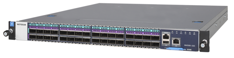
M4500-32C Front
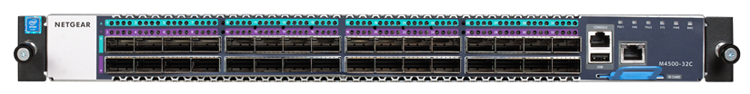
M4500-48XF8C Front
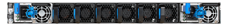
M4500-32C Back

M4500-48XF8C Back
Components:
M4500-32C 100GE Managed Switch
- The M4500-32C provides 32-port QSFP28 (100G, 50G and 40G)
- QSFP28 ports are preconfigured for 100G
- 6.4Tbps non-blocking fabric for 32 x 100G bi-directional
- Two modular power supplies APS750W are pre-installed for 1+1 redundancy
- Six modular fan trays AFT402 are pre-installed for 4+2 redundancy
- Two mounting ears and screws for rack mounting (front)
- One set of rail kits for rack mounting (back)
- Out-of-band 1G Ethernet Management port
- RJ45 RS232 console port and USB storage port
- L2/L3/L4 rich services for AV over IP (certified SDVoE-ready)
- Enhanced IGMP Plus for plug & play L2 Multicast between M4300/M4500 switches
- Line-rate spine and leaf with M4500-48XF8C (48-port SFP28 and 8-port QSFP28)
- Static and dynamic routing with VRRP, OSPF, BGP, VRF-Lite and PIM-SM/SSM
- 64dB @25°C / 77°F
M4500-32C Front
M4500-32C Back
M4500-48XF8C 25/100GE Managed Switch
- The M4500-48XF8C switch provides 48-port SFP28 (25G, 10G and 1G fiber)
- And it also provides 8-port QSFP28 (100G, 50G and 40G fiber)
- SFP28 ports are preconfigured for 10G, QSFP28 ports for 100G
- 4Tbps non-blocking fabric for 48 x 25G and 8 x 100G bi-directional
- Two modular power supplies APS750W are pre-installed for 1+1 redundancy
- Six modular fan trays AFT402 are pre-installed for 4+2 redundancy
- Two mounting ears and screws for rack mounting (front)
- One set of rail kits for rack mounting (back)
- Out-of-band 1G Ethernet Management port
- RJ45 RS232 console port and USB storage port
- L2/L3/L4 rich services for AV over IP (certified SDVoE-ready)
- Enhanced IGMP Plus for plug & play L2 Multicast between M4300/M4500 switches
- Line-rate spine and leaf with M4500-32C (32-port QSFP28)
- Static and dynamic routing with VRRP, OSPF, BGP, VRF-Lite and PIM-SM/SSM
- 68dB @25°C / 77°F
M4500-32C Front
M4500-32C Back
Specifications:
| Switching Features | |
| VLAN Support | VLANs are collections of switching ports that comprise a single broadcast domain. Packets are classified as belonging to a VLAN based on either the VLAN tag or a combination of the ingress port and packet contents. Packets sharing common attributes can be groups in the same VLAN. The switch software is in full compliance with IEEE 802.1Q VLAN tagging. |
| Double VLAN | The Double VLAN feature (IEEE 802.1QinQ) allows the use of a second tag on network traffic. The additional tag helps differentiate between customers in the Metropolitan Area Networks (MAN) while preserving individual customer's VLAN identification when they enter their own 802.1Q domain. |
| Switching Modes | The switchport mode feature helps to minimize the potential for configuration errors. The feature also makes VLAN configuration easier by reducing the amount of commands needed for port configuration. For example, to configure a port connected to an end user, you can configure the port in Access mode. Ports connected to other switches can be configured in Trunk mode. VLAN assignments and tagging behavior are automatically configured as appropriate for the connection type. |
| Spanning Tree Protocols (STP) | Spanning Tree Protocol (IEEE 802.1D) is a standard requirement of Layer 2 switches that allows bridges to automatically prevent and resolve L2 forwarding loops. The STP feature supports a variety of per-port settings including path cost, priority settings, Port Fast mode, STP Root Guard, Loop Guard, TCN Guard, and Auto Edge. These settings are also configurable per-Port-channel. |
| Rapid Spanning Tree | Rapid Spanning Tree Protocol (RSTP) detects and uses network topologies to enable faster spanning tree convergence after a topology change, without creating forwarding loops. The port settings supported by STP are also supported by RSTP. |
| Multiple Spanning Tree | Multiple Spanning Tree (MSTP) operation maps VLANs to spanning tree instances. Packets assigned to various VLANs are transmitted along different paths within MSTP Regions (MST Regions). Regions are one or more interconnected MSTP bridges with identical MSTP settings. The MSTP standard lets administrators assign VLAN traffic to unique paths. M4500 supports IEEE 802.1Q-2005, which is a version of corrected problems associated with the previous version. It provides for faster transition-to-forwarding, and incorporates new features for a port (restricted role and restricted TCN). |
| Bridge Protocol Data Unit (BPDU) Guard | Spanning Tree BPDU Guard is used to disable the port in case a new device tries to enter the already existing topology of STP. Thus devices, which were originally not a part of STP, are not allowed to influence the STP topology. |
| Port-channel | Up to 32 ports can combine to form a single Port-Channel (LAG). This enables fault tolerance protection from physical link disruption, higher bandwidth connections and improved bandwidth granularity. A Port-channel is composed of ports of the same speed, set to full-duplex operation |
| Link Aggregate Control Protocol (LACP) | Link Aggregate Control Protocol (LACP) uses peer exchanges across links to determine, on an ongoing basis, the aggregation capability of various links, and continuously provides the maximum level of aggregation capability achievable between a given pair of systems. LACP automatically determines, configures, binds, and monitors the binding of ports to aggregators within the system. |
| Multi Chassis Link Aggregation Group (MLAG) | This feature enables a Port-channel to be created across two independent units, which creates a scenario where some member ports of the MLAG can reside on one unit and the other members of the MLAG can reside on the other unit. The partner device on the remote side can be a MLAG unaware unit. For the MLAG unaware unit, the MLAG appears to be a single Port-channel connected to a single unit. |
| Flow Control Support (IEEE 802.3x) | Flow control enables lower speed switches to communicate with higher speed switches by requesting that the higher speed switch refrains from sending packets. Transmissions are temporarily halted to prevent buffer overflows. |
| Asymmetric Flow Control | When in asymmetric flow control mode, the switch responds to PAUSE frames received from peers by stopping packet transmission, but the switch does not initiate MAC control PAUSE frames. When the switch is configured in asymmetric flow control (or no flow control mode), the device is placed in egress drop mode. Egress drop mode maximizes the throughput of the system at the expense of packet loss in a heavily congested system, and this mode avoids head of line blocking. Asymmetric flow control is not supported on Fast Ethernet platforms because support was introduced to the physical layer with the Gigabit PHY specifications. |
| Alternate Store and Forward (ASF) | The Alternate Store and Forward (ASF) feature, which is also known as cut-through mode, reduces latency for large packets. When ASF is enabled, the memory management unit (MMU) can forward a packet to the egress port before it has been entirely received on the Cell Buffer Pool (CBP) memory. |
| Jumbo Frames Support | Jumbo frames enable transporting data in fewer frames to ensure less overhead, lower processing time, and fewer interrupts. The maximum transmission unit (MTU) size is configurable per-port (max 9K). |
| Auto-MDI/MDIX Support | M4500 supports auto-detection between crossed and straight-through cables. Media-Dependent Interface (MDI) is the standard wiring for end stations, and the standard wiring for hubs and switches is known as Media- Dependent Interface with Crossover (MDIX). |
| Unidirectional Link Detection (UDLD) | The UDLD feature detects unidirectional links physical ports by exchanging packets containing information about neighboring devices. The purpose of the UDLD feature is to detect and avoid unidirectional links. A unidirectional link is a forwarding anomaly in a Layer 2 communication channel in which a bidirectional link stops passing traffic in one direction. |
| Expandable Port Configuration | Expandable ports allow you to configure a 100GbE port in either 4x25/10GbE mode or 1x40GbE mode. When the 100GbE port is operating in 4x25/10GbE mode, the port operates as four 25/10GbE ports, each on a separate lane. This mode requires the use of a suitable 4x25GbE to 1x100GbE pigtail cable. Expandable port capability can be enabled on 100G ports using the CLI command [no] port-mode. A change to the port mode is made effective immediately. |
| Port Speed Configuration | M4500-48XF8C provides 48 ports SFP28 pre-configured for 10Gbps. Port speed can be 25Gbps, 10Gbps or 1Gbps. SFP28 port speed is only configurable by multiples of 4 ports using the CLI command [no] port-mode. For instance, configuring Port-1 using (M4500-48XF8C) (Interface 0/1)#port-mode 4x1G is actually setting all ports 1, 2, 3 and 4 at 1Gbps speed. Configuring Port-5 using (M4500-48XF8C) (Interface 0/5)#port-mode 4x1G is setting all ports 5, 6, 7 and 8 at 1Gbps speed. |
| VLAN-aware MAC-based Switching | Packets arriving from an unknown source address are sent to the CPU and added to the Hardware Table. Future packets addressed to or from this address are more efficiently forwarded. |
| Back Pressure Support | On half-duplex links, a receiver may prevent buffer overflows by jamming the link so that it is unavailable for additional traffic. On full duplex links, a receiver may send a PAUSE frame indicating that the transmitter should cease transmission of frames for a specified period. When flow control is enabled, the switch will observe received PAUSE frames or jamming signals, and will issue them when congested. |
| Auto Negotiation | Auto negotiation allows the switch to advertise modes of operation. The auto negotiation function provides the means to exchange information between two switches that share a point-to-point link segment, and to automatically configure both switches to take maximum advantage of their transmission capabilities. The switch enhances auto negotiation by providing configuration of port advertisement. Port advertisement allows the system administrator to configure the port speeds that are advertised. |
| Storm Control | When Layer 2 frames are forwarded, broadcast, unknown unicast, and multicast frames are flooded to all ports on the relevant virtual local area network (VLAN). The flooding occupies bandwidth, and loads all nodes connected on all ports. Storm control limits the amount of broadcast, unknown unicast, and multicast frames accepted and forwarded by the switch. Per-port and per-storm control type (broadcast, multicast, or unicast), the storm control feature can be configured to automatically shut down a port when a storm condition is detected on the port; or to send a trap to the system log. When configured to shut down, the port is put into a diagnostic-disabled state. The user must manually re-enable the interface for it to be operational. When configured to send a trap, the trap is sent once in every 30 seconds. When neither action is configured, the switch rate-limits the traffic when storm conditions occur. |
| Port Mirroring | Port mirroring monitors and mirrors network traffic by forwarding copies of incoming and outgoing packets from up to four source ports to a monitoring port. The switch also supports flow-based mirroring, which allows you to copy certain types of traffic to a single destination port. This provides flexibility-instead of mirroring all ingress or egress traffic on a port the switch can mirror a subset of that traffic. You can configure the switch to mirror flows based on certain kinds of Layer 2, Layer 3, and Layer 4 information. The switch supports up to four monitor sessions. Port mirroring, flow based mirroring, RSPAN, and VLAN mirroring can be configured at the same time on the switch using different sessions IDs and in any combinations. Any two sessions cannot be identical. Multiple mirroring sessions are supported for all types of mirroring. A given interface can be used as a source interface for different sessions. For example a mirroring session can be created with source interface as port A and destination interface as port B. Another session can be created with source interface as port A and destination interface as port C. An interface cannot be configured as a destination interface for more than one session. An IP/MAC access-list can be attached to any mirroring session or to all sessions at the same time. |
| sFlow | sFlow is the standard for monitoring high-speed switched and routed networks. sFlow technology is built into network equipment and gives complete visibility into network activity, enabling effective management and control of network resources. The switch supports sFlow version 5. |
| Static and Dynamic MAC Address Tables | You can add static entries to the switch's MAC address table and configure the aging time for entries in the dynamic MAC address table. You can also search for entries in the dynamic table based on several different criteria. |
| Link Layer Discovery Protocol (LLDP) | The IEEE 802.1AB defined standard, Link Layer Discovery Protocol (LLDP), allows the switch to advertise major capabilities and physical descriptions. This information can help you identify system topology and detect bad configurations on the LAN. |
| Link Layer Discovery Protocol (LLDP) for Media Endpoint Device | The Link Layer Discovery Protocol for Media Endpoint Devices (LLDP-MED) provides an extension to the LLDP standard for network configuration and policy, device location, Power over Ethernet management, and inventory management. |
| DHCP Layer 2 Relay | This feature permits Layer 3 Relay agent functionality in Layer 2 switched networks. The switch supports L2 DHCP relay configuration on individual ports, Port-channels and VLANs. |
| MAC Multicast Support | Multicast service is a limited broadcast service that allows one-to-many and many-to-many connections. In Layer 2 multicast services, a single frame addressed to a specific multicast address is received, and copies of the frame to be transmitted on each relevant port are created. |
| IGMP Snooping | Internet Group Management Protocol (IGMP) Snooping is a feature that allows a switch to forward multicast traffic intelligently on the switch. Multicast IP traffic is traffic that is destined to a host group. Host groups are identified by class D IP addresses, which range from 224.0.0.0 to 239.255.255.255. Based on the IGMP query and report messages, the switch forwards traffic only to the ports that request the multicast traffic. This prevents the switch from broadcasting the traffic to all ports and possibly affecting network performance. |
| IGMP Plus Enhancement | The IGMP Plus enhanced implementation for automatic multicast across a M4500 / M4300 L2 network (Spine and Leaf topologies) removes the need for L3 PIM routing: o IGMP Plus is pre-configured on default VLAN 1 out of the box in all M4500 and M4300 models (M4300: starting 12.0.8.x release). o IGMP Plus can be configured on another VLAN for automatic IGMP across switches on that VLAN (uplinks can make part of that VLAN in trunk mode). o IGMP Plus allows AV-over-IP devices (TX/Encoders and RX/Decoders) to be connected across multiple M4500 and M4300 switches in a star topology. o New show igmpsnooping group command in CLI displays the Source and Group IP addresses along with their corresponding MAC addresses that are learnt through IGMP Snooping in a given VLAN on a given interface. |
| Source Specific Multicasting (SSM) | This mechanism provides the ability for a host to report interest in receiving a particular multicast stream only from among a set of specific source addresses, or its interest in receiving a multicast stream from any source other than a set of specific source addresses. |
| Control Packet Flooding | This feature enhances the MGMD Snooping functionality to flood multicast packets with DIP=224.0.0.x to all members of the incoming VLAN irrespective of the configured filtering behavior. This enhancement depends on the ability of the switch to flood packets with DIP=224.0.0.x irrespective of the entries in the L2 Multicast Forwarding Tables. |
| Flooding to mRouter Ports | This feature enhances the MGMD Snooping functionality to flood unregistered multicast streams to all mRouter ports in the VLAN irrespective of the configured filtering behavior. This enhancement depends on the ability of the switch to flood packets to specific ports in the incoming VLAN when there are no entries in the L2 Multicast Forwarding Tables for the specific stream. In platforms that do not have the hardware capability, incoming multicast streams are always flooded in the ingress VLAN when the switch supports an "L2 multicast miss." |
| IGMP Snooping Querier | When Protocol Independent Multicast (PIM) and IGMP are enabled in a network with IP multicast routing, the IP multicast router acts as the IGMP querier. However, if it is desirable to keep the multicast network Layer 2 switched only, the IGMP Snooping Querier can perform the query functions of a Layer 3 multicast router. |
| Management and Control Plane ACLs | This feature provides hardware-based filtering of traffic to the CPU. An optional 'management' feature is available to apply the ACL on the CPU port. Currently, control packets like BPDU are dropped because of the implicit 'deny all' rule added at the end of the list. To overcome this rule, you must add rules that allow the control packets. Support for user-defined simple rate limiting rule attributes for inbound as well as outbound traffic is also available. This attribute is supported on all QoS capable interfaces - physical, Port-channel, and control-plane. |
| Remote Switched Port Analyzer (RSPAN) | Along with the physical source ports, the network traffic received/transmitted on a VLAN can be monitored. A port mirroring session is operationally active if and only if both a destination (probe) port and at least one source port or VLAN is configured. If neither is true, the session is inactive. The switch supports remote port mirroring. The switch also supports VLAN mirroring. Traffic from/to all the physical ports which are members of that particular VLAN is mirrored (The source for a port mirroring session can be either physical ports or VLAN). For Flow-based mirroring, ACLs are attached to the mirroring session. The network traffic that matches the ACL is only sent to the destination port. This feature is supported for remote monitoring also. IP/MAC access-list can be attached to the mirroring session. Up to four RSPAN sessions can be configured on the switch and up to four RSPAN VLANs are supported. An RSPAN VLAN cannot be configured as a source for more than one session at the same time. To configure four RSPAN mirroring sessions, it is required to configure 4 RSPAN VLANs. |
| Link Dependency | The Link Dependency feature supports enabling/disabling ports based on the link state of other ports (i.e., making the link state of some ports dependent on the link state of others). In the simplest form, if port A is dependent on port B and switch detects link loss on B, the switch automatically brings down link on port A. When the link is restored to port B, the switch automatically restores link to port A. The link action command option determines whether link A will come up/go down, depending upon the state of link B. |
| IPv6 Router Advertisement Guard | M4500 supports IPv6 Router Advertisement Guard (RA-Guard) to protect against attacks via rogue Router Advertisements in accordance with RFC 6105. RA Guard supports Stateless RA-Guard, for which you can configure the interface to allow received router advertisements and router redirect message to be processed/forwarded or dropped. By default, RA-Guard is not enabled on any interfaces. RA-Guard is enabled/disabled on physical interfaces or Port-channels. RA-Guard does not require IPv6 routing to be enabled. |
| FIP Snooping | The FCoE Initialization Protocol (FIP) is used to perform the functions of FC_BB_E device discovery, initialization, and maintenance. FIP uses a separate EtherType from FCoE to distinguish discovery, initialization, and maintenance traffic from other FCoE traffic. FIP frames are standard Ethernet size (1518 Byte 802.1q frame), whereas FCoE frames are a maximum of 2240 bytes. FIP snooping is a frame inspection method used by FIP Snooping Bridges to monitor FIP frames and apply policies based upon the L2 header information in those frames. FIP snooping allows for: o Auto-configuration of Ethernet ACLs based on information in the Ethernet headers of FIP frames. o Emulation of FC point-to-point links within the DCB Ethernet network. o Enhanced FCoE security/robustness by preventing FCoE MAC spoofing. The role of FIP snooping-enabled ports on the switch falls under one of the following types: o Perimeter or Edge port (connected directly to a Fiber Channel end node or ENode). o Fiber Channel forwarder (FCF) facing port (that receives traffic from FCFs targeted to the ENodes). Note: The FIP Snooping Bridge feature supports the configuration of the perimeter port role and FCF- facing port roles and is intended for use only at the edge of the switched network. The default port role in an FCoE-enabled VLAN is as a perimeter port. FCF-facing ports are configured by the user. |
| ECN Support | Explicit Congestion Notification (ECN) is defined in RFC 3168. Conventional TCP networks signal congestion by dropping packets. A Random Early Discard scheme provides earlier notification than tail drop by dropping packets already queued for transmission. ECN marks congested packets that would otherwise have been dropped and expects an ECN capable receiver to signal congestion back to the transmitter without the need to retransmit the packet that would have been dropped. For TCP, this means that the TCP receiver signals a reduced window size to the transmitter but does not request retransmission of the CE marked packet. M4500 implements ECN capability as part of the WRED configuration process. It is configured as parameter in the random-detect command. Eligible packets are marked by hardware based upon the WRED configuration. You can configure any CoS queue to operate in ECN marking mode and can configure different discard thresholds for each color. |
| Security features | |
| Configurable Access and Authentication Profiles | You can configure rules to limit access to the switch management interface based on criteria such as access type and source IP address of the management host. You can also require the user to be authenticated locally or by an external server, such as a RADIUS server. |
| AAA Command Authorization | This feature enables AAA Command Authorization on the switch. |
| Password-protected Management Access | Access to the CLI and SNMP management interfaces is password protected, and there are no default users on the system. |
| Strong Password Enforcement | The Strong Password feature enforces a baseline password strength for all locally administered users. Password strength is a measure of the effectiveness of a password in resisting guessing and brute-force attacks. The strength of a password is a function of length, complexity and randomness. Using strong passwords lowers overall risk of a security breach. |
| MAC-based Port Security | The port security feature limits access on a port to users with specific MAC addresses. These addresses are manually defined or learned on that port. When a frame is seen on a locked port, and the frame source MAC address is not tied to that port, the protection mechanism is invoked. |
| RADIUS Client | The switch has a Remote Authentication Dial In User Service (RADIUS) client and can support up to 32 authentication and accounting RADIUS servers. |
| TACACS+ Client | The switch has a TACACS+ client. TACACS+ provides centralized security for validation of users accessing the switch. TACACS+ provides a centralized user management system while still retaining consistency with RADIUS and other authentication processes. |
| Dot1x Authentication (IEEE 802.1X) | Dot1x authentication enables the authentication of system users through a local internal server or an external server. Only authenticated and approved system users can transmit and receive data. Supplicants are authenticated using the Extensible Authentication Protocol (EAP). Also supported are PEAP, EAP-TTL, EAP- TTLS, and EAP-TLS. M4500 supports RADIUS-based assignment (via 802.1X) of VLANs, including guest and unauthenticated VLANs. The Dot1X feature also supports RADIUS-based assignment of filter IDs as well as MAC-based authentication, which allows multiple supplicants connected to the same port to each authenticate individually. |
| MAC Authentication Bypass | The switch supports the MAC-based Authentication Bypass (MAB) feature, which provides 802.1x- unaware clients (such as printers and fax machines) controlled access to the network using the devices' MAC address as an identifier. This requires that the known and allowable MAC address and corresponding access rights be pre-populated in the authentication server. MAB works only when the port control mode of the port is MAC- based. |
| DHCP Snooping | DHCP Snooping is a security feature that monitors DHCP messages between a DHCP client and DHCP server. It filters harmful DHCP messages and builds a bindings database of (MAC address, IP address, VLAN ID, port) tuples that are specified as authorised. DHCP snooping can be enabled globally and on specific VLANs. Ports within the VLAN can be configured to be trusted or untrusted. DHCP servers must be reached through trusted ports. This feature is supported for both IPv4 and IPv6 packets. |
| DHCPv6 Snooping | In an IPv6 domain, a node can obtain an IPv6 address using the following mechanisms: o IPv6 address auto-configuration using router advertisements o The DHCPv6 protocol In a typical man-in-the-middle (MiM) attack, the attacker can snoop or spoof the traffic act as a rogue DHCPv6 server. To prevent such attacks, DHCPv6 snooping helps to secure the IPv6 address configuration in the network. DHCPv6 snooping enables the Brocade device to filter untrusted DHCPv6 packets in a subnet on an IPv6 network. DHCPv6 snooping can ward off MiM attacks, such as a malicious user posing as a DHCPv6 server sending false DHCPv6 server reply packets with the intention of misdirecting other users. DHCPv6 snooping can also stop unauthorised DHCPv6 servers and prevent errors due to user misconfiguration of DHCPv6 servers. |
| Dynamic ARP Inspection | Dynamic ARP Inspection (DAI) is a security feature that rejects invalid and malicious ARP packets. The feature prevents a class of man-in-the-middle attacks, where an unfriendly station intercepts traffic for other stations by poisoning the ARP caches of its unsuspecting neighbors. The malicious station sends ARP requests or responses mapping another station's IP address to its own MAC address. |
| IP Source Address Guard | IP Source Guard and Dynamic ARP Inspection use the DHCP snooping bindings database. When IP Source Guard is enabled, the switch drops incoming packets that do not match a binding in the bindings database. IP Source Guard can be configured to enforce just the source IP address or both the source IP address and source MAC address. Dynamic ARP Inspection uses the bindings database to validate ARP packets. This feature is supported for both IPv4 and IPv6 packets. |
| Quality of Service Features | |
| Access Control Lists (ACL) | Access Control Lists (ACLs) ensure that only authorised users have access to specific resources while blocking off any unwarranted attempts to reach network resources. ACLs are used to provide traffic flow control, restrict contents of routing updates, decide which types of traffic are forwarded or blocked, and above all provide security for the network. M4500 supports the following ACL types: o IPv4 ACLs o IPv6 ACLs o MAC ACLs For all ACL types, you can apply the ACL rule when the packet enters or exits the physical port, Port-channel, or VLAN interface (ingress and egress ACLs). |
| ACL Remarks | Users can use ACL remarks to include comments for ACL rule entries in any MAC ACL. Remarks assist the user in understanding ACL rules easily. |
| ACL Rule Priority | This feature allows user to add sequence numbers to ACL rule entries and re-sequence them. When a new ACL rule entry is added, the sequence number can be specified so that the new ACL rule entry is placed in the desired position in the access list. |
| Differentiated Service (DIffServ) | The QoS Differentiated Services (DiffServ) feature allows traffic to be classified into streams and given certain QoS treatment in accordance with defined per-hop behaviors. The switch supports both IPv4 and IPv6 packet classification. |
| Class of Service (CoS) | The Class of Service (CoS) queueing feature lets you directly configure certain aspects of switch queuing. This provides the desired QoS behavior for different types of network traffic when the complexities of DiffServ are not required. CoS queue characteristics, such as minimum guaranteed bandwidth and transmission rate shaping, are configurable at the queue (or port) level. |
| Management Features | |
| Management Options | You can use the following methods to manage the switch: o Use a telnet client, SSH client, or a direct console connection to access the CLI. The CLI syntax and semantics conform as much as possible to common industry practice. o Use a network management system (NMS) to manage and monitor the system through SNMP. M4500 supports SNMP v1/v2c/v3 over the UDP/IP transport protocol. |
| Management of Basic Network Information | The DHCP client on the switch allows the switch to acquire information such as the IP address and default gateway from a network DHCP server. You can also disable the DHCP client and configure static network information. Other configurable network information includes a Domain Name Server (DNS), host name to IP address mapping, and a default domain name. M4500 also includes a DHCPv6 client for acquiring IPv6 addresses, prefixes, and other IPv6 network configuration information. |
| File Management | You can upload and download files such as configuration files and system images by using TFTP, Secure FTP (SFTP), or Secure Copy (SCP). Configuration file uploads from the switch to a server are a good way to back up the switch configuration. You can also download a configuration file from a server to the switch to restore the switch to the configuration in the downloaded file. |
| Malicious Code Detection | This feature provides a mechanism to detect the integrity of the image, if the software binary is corrupted or tampered with while end user attempts to download the software image to the switch. This release addresses this problem by using digital signatures to verify the integrity of the binary image. It also provides flexibility to download a digitally signed configuration script and verify the digital signature to ensure the integrity of the downloaded configuration file. |
| Automatic Installation of Firmware and Configuration | The Auto Install feature allows the switch to upgrade the configuration file automatically during device initialization with limited administrative configuration on the device. The switch can obtain the necessary information from a DHCP server on the network. |
| Warm Reboot | The Warm Reboot feature reduces the time it takes to reboot the switch thereby reducing the traffic disruption in the network during a switch reboot. For a typical switch, the traffic disruption is reduced from about two minutes for a cold reboot to about 20 seconds for a warm reboot. |
| SNMP Alarms and Trap Logs | The system logs events with severity codes and timestamps. The events are sent as SNMP traps to a trap recipient list. |
| Remote Monitoring (RMON) | RMON is a standard Management Information Base (MIB) that defines current and historical MAC-layer statistics and control objects, allowing real-time information to be captured across the entire network. The data collected is defined in the RMON MIB, RFC 2819 (32-bit counters), RFC 3273 (64-bit counters), and RFC 3434 (High Capacity Alarm Table). |
| Statistics Application | The statistics application collects the statistics at a configurable time interval. The user can specify the port number(s) or a range of ports for statistics to be displayed. The configured time interval applies to all ports. Detailed statistics are collected between the specified time range in date and time format. The time range can be defined as having an absolute time entry and/or a periodic time. For example, a user can specify the statistics to be collected and displayed between 9:00 15 OCT 2019 (START) and 21:00 15 OCT 2019 (END) or schedule it on every MON, WED and FRI 9:00 (START) to 21:00 (END). The user receives these statistics in a number of ways as listed below: o User requests through CLI for a set of counters. o User can configure the device to display statistics using syslog or email alert. The syslog or email alert messages are sent by statistics application at END time. The statistics are presented on the console at END time. |
| Log Messages | The switch maintains in-memory log messages as well as persistent logs. You can also configure remote logging so that the switch sends log messages to a remote log server. You can also configure the switch to send log messages to a configured SMTP server. This allows you to receive the log message in an e-mail account of your choice. Switch auditing messages, CLI command logging, and SNMP logging can be enabled or disabled. |
| System Time Management | The switch will obtain the system time and date through NTP (Network Time Protocol) service of Linux server, or you can set the time and date locally or configure the time zone on the switch via Linux. |
| Source IP Address Configuration | Syslog, TACACS, SNTP, sFlow, SNMP Trap, RADIUS, and DNS Clients allow the IP Stack to select the source IP address while generating the packet. This feature provides an option for the user to select an interface for the source IP address while the management protocol transmits packets to management stations. The source address is specified for each protocol. |
| Multiple Linux Routing Tables | On Linux systems, local and default IPv4 routes for the service port and network port are installed in routing tables dedicated to each management interface. Locally-originated IPv4 packets use these routing tables when the source IP address of the packet matches an address on one of these interfaces. This feature allows the Linux IP stack to use default routes for different interfaces simultaneously. |
| Open Network Install Environment Support | Open Network Install Environment (ONIE) allows customers to install their choice of network operating system (NOS) onto a switch. When the switch boots, ONIE enables the switch to fetch a NOS stored on a remote server. The remote server can hold multiple NOS images, and you can specify which NOS to load and run on the switch. ONIE support in the switch software facilitates automated data center provisioning by enabling a bare-metal network switch ecosystem. ONIE is a small operating system. It is preinstalled as firmware and requires an ONIE-compliant boot loader (U-Boot/BusyBox), a kernel (Linux) and the ONIE discovery and execution application. For more information about ONIE, see http://onie.github.io/onie. |
| Interface Error Disable and Auto Recovery | If the switch detects an error condition for an interface, it places the interface in the diagnostic disabled state by shutting down the interface. The error-disabled interface does not allow any traffic until it is reenabled. You can manually reenable the interface, or, if the Auto Recovery feature is enabled, the interface can be reenabled automatically after a configurable time-out period. There are multiple reasons that may cause the switch to place an interface in the error-disabled state. Auto Recovery can be configured to take effect if an interface is error-disabled for any reason, or for some reasons but not others. |
| CLI Scheduler | The CLI scheduler allows administrators to schedule fully-qualified EXEC mode CLI commands to run once, at specified intervals, at specified calendar dates and times, or upon system startup. CLI scheduler has two basic processes. A policy list is configured containing lines of fully-qualified EXEC CLI commands to be run at the same time or same interval. One or more policy lists are then scheduled to run after a specified interval of time, at a specified calendar date and time, or upon system startup. Each scheduled occurrence can be set to run either once only or on a recurring basis. |
| Routing Features | |
| IP Unnumbered | Each routing interface can be configured to borrow the IP address from the loopback interfaces and use this IP for all routing activities. The IP Unnumbered feature was initially developed to avoid wasting an entire subnet on point-to-point serial links. The IP Unnumbered feature can also be used in situations where adjacencies are transient and adjacent interfaces cannot be easily configured with IPv4 addresses in the same subnet. It also helps in reducing the configuration overhead in large scale Data-Center deployments. |
| Open Shortest Path First (OSPF) | Open Shortest Path First (OSPF) is a dynamic routing protocol commonly used within medium-to-large enterprise networks. OSPF is an interior gateway protocol (IGP) that operates within a single autonomous system. |
| Border Gateway Protocol (BGP) | BGP is an exterior routing protocol used in large-scale networks to transport routing information between autonomous systems (AS). As an interdomain routing protocol, BGP is used when AS path information is required to provide partial or full Internet routing downstream. The switch supports BGP version 4. The following BGP features are supported: o Proprietary BGP MIB support for reporting status variables and internal counters. o Additional route map support: Match as-path; Set as-path; Set local-preference; Set metric o Support for inbound and outbound neighbor-specific route maps. o Handles the BGP RTO full condition. o Support for the show ip bgp command. o Support for the show ip bgp traffic command. o Support for the bgp always-compare-med command. o Support for the maximum number of BGP neighbors: 128. o A prefix list is supported to filter the output of the show ip bgp command. o Configurable maximum length of a received AS_PATH. o Show command to list the routes accepted from a specific neighbor. o Show command to list the routes rejected from a specific neighbor. o Support for BGP communities. o Support for IPv6. o IPv6 Transport and Prefix list o Support for BGP peer templates to simplify neighbor configuration. |
| VLAN Routing | M4500 supports VLAN routing. You can also configure the software to allow traffic on a VLAN to be treated as if the VLAN were a router port |
| IP Configuration | M4500 IP configuration settings to allow you to configure network information for VLAN routing interfaces such as IP address and subnet mask, MTU size, and ICMP redirects. Global IP configuration settings for the switch allow you to enable or disable the generation of several types of ICMP messages and enable or disable the routing mode. |
| Address Resolution Protocol (ARP) Table Management | You can create static ARP entries and manage many settings for the dynamic ARP table, such as age time for entries, retries, and cache size. |
| BOOTP/DHCP Relay Agent | The switch BOOTP/DHCP Relay Agent feature relays BOOTP and DHCP messages between DHCP clients and DHCP servers that are located in different IP subnets. |
| IP Helper and UDP Relay | The IP Helper and UDP Relay features provide the ability to relay various protocols to servers on a different subnet. |
| Routing Table | The routing table displays information about the routes that have been dynamically learned. You can configure static and default routes and route preferences. A separate table shows the routes that have been manually configured. |
| Virtual Router Redundancy Protocol (VRRP) | VRRP provides hosts with redundant routers in the network topology without any need for the hosts to reconfigure or know that there are multiple routers. If the primary (master) router fails, a secondary router assumes control and continues to use the virtual router IP (VRIP) address. VRRP Route Interface Tracking extends the capability of VRRP to allow tracking of specific route/interface IP states within the router that can alter the priority level of a virtual router for a VRRP group. |
| Algorithmic Longest Prefix Match (ALPM) | Algorithmic Longest Prefix Match (ALPM) is a protocol used by routers to select an entry from a forwarding table. When an exact match is not found in the forwarding table, the match with the longest subnet mask, also called longest prefix match, is chosen. It is called the longest prefix match because it is also the entry where the largest number of leading address bits of the destination address match those in the table entry.ALPM enables support for large number of routes. (For BGP, 32k IPv4 routes and 24k IPv6 are supported.) The SDM template, "dual-ipv4-and-ipv6 alpm" is available to accommodate a large number of routes. |
| Bidirectional Forwarding Detection | Bidirectional Forwarding Detection (BFD) is presented as a service to its user applications, providing the options to create and destroy a session with a peer device and reporting upon the session status. On the switch, OSPF and BGP can use BFD for monitoring of their neighbors' availability in the network and for fast detection of connection faults with them. |
| VRF Lite Operation and Configuration | The Virtual Routing and Forwarding feature enables a router to function as multiple routers. Each virtual router manages its own routing domain, with its own IP routes, routing interfaces, and host entries. Each virtual router makes its own routing decisions, independent of other virtual routers. More than one virtual routing table may contain a route to a given destination. The network administrator can configure a subset of the router's interfaces to be associated with each virtual router. The router routes packets according to the virtual routing table associated with the packet's ingress interface. Each interface can be associated with at most one virtual router. |
| Layer 3 Multicast Features | |
| Internet Group Management Protocol | The Internet Group Management Protocol (IGMP) is used by IPv4 systems (hosts and routers) to report their IP multicast group memberships to any neighboring multicast routers. The switch performs the "multicast router part" of the IGMP protocol, which means it collects the membership information needed by the active multicast router. |
| PIM Sparse Mode (PIM-SM) | Protocol Independent Multicast-Sparse Mode (PIM-SM) is used to efficiently route multicast traffic to multicast groups that may span wide area networks, and where bandwidth is a constraint. PIM-SM uses shared trees by default and implements source-based trees for efficiency. This data threshold rate is used to toggle between trees. |
| PIM Source Specific Multicast (PIM-SSM) | Protocol Independent Multicast-Source Specific Multicast (PIM-SSM) is a subset of PIM-SM and is used for one-to-many multicast routing applications, such as audio or video broadcasts. PIM-SSM does not use shared trees. |
| PIM IPv6 | PIM-SM support IPv6 routes. |
| MLD/MLDv2 (RFC 2710 / RFC 3810) | MLD is used by IPv6 systems (listeners and routers) to report their IP multicast addresses memberships to any neighboring multicast routers. The implementation of MLD v2 is backward compatible with MLD v1. MLD protocol enables the IPv6 router to discover the presence of multicast listeners, the nodes that want to receive the multicast data packets, on its directly attached interfaces. The protocol specifically discovers which multicast addresses are of interest to its neighboring nodes and provides this information to the multicast routing protocol that make the decision on the flow of the multicast data packets. |
| Datacenter Features | |
| Priority-Based Flow Control | The Priority-Based Flow Control (PFC) feature allows the user to pause or inhibit transmission of individual priorities within a single physical link. By configuring PFC to pause a congested priority (priorities) independently, protocols that are highly loss sensitive can share the same link with traffic that has different loss tolerances. Priorities are differentiated by the priority field of the 802.1Q VLAN header. An interface that is configured for PFC is automatically disabled for 802.3x flow control. |
| Data Center Bridging Exchange Protocol | The Data Center Bridging Exchange Protocol (DCBX) is used by data center bridge devices to exchange configuration information with directly-connected peers. The protocol is also used to detect misconfiguration of the peer DCBX devices and optionally, for configuration of peer DCBX devices |
| CoS Queuing and Enhanced Transmission Selection | The CoS Queuing feature allows the switch administrator to directly configure certain aspects of the device hardware queuing to provide the desired QoS behavior for different types of network traffic. The priority of a packet arriving at an interface can be used to steer the packet to the appropriate outbound CoS queue through a mapping table. CoS queue characteristics such as minimum guaranteed bandwidth, transmission rate shaping, etc. are user configurable at the queue (or port) level. Enhanced Transmission Selection (ETS) allows Class of Service (CoS) configuration settings to be advertised to other devices in a data center network through DCBX ETS TLVs. CoS information is exchanged with peer DCBX devices using ETS TLVs. |
| VXLAN Gateway | Logically segregated virtual networks in a data center are sometimes referred to as data center VPNs. The VXLAN Gateway is a solution that allows VXLAN to communicate with another network, particularly a VLAN. It offers VXLAN Tunnel Endpoint (VTEP) functionality for VXLAN tunnels on the switch. VXLAN is a layer-3 function, IP-based technologies that prepend an existing layer-2 frame with a new IP header, providing layer-3 based tunneling capabilities for layer-2 frames. This essentially enables a layer-2 domain to extend across a layer-3 boundary. For the traffic from a VXLAN to use services on physical devices in a distant network, the traffic must pass through a VXLAN Gateway.The VXLAN Gateway feature is configurable through the CLI. It also offers an Overlay API to facilitate programming from external agents. |
Documentation:
Download the NETGEAR M4500 Series Datasheet (PDF).
Pricing Notes:
- All Prices are Inclusive of GST
- Pricing and product availability subject to change without notice.
Our Price: Request a Quote